Table of Content
With the help of program, we are implementing the encoder and decoder actions in Arduino. Similar actions are performed when other switches are pushed. As a result, the relay connected to load 1 is activated and the load is turned on. The 434 MHz Radio Frequency Transmitter – Receiver Module is the best and cheapest way to implement a wireless communication for a reasonably longer ranges.
The system can be expanded to a smart home system with security by integrating several sensors like temperature, humidity, light and security devices like burglar sensors, CCTV’s etc. You'll have to adjust the code based on what temperatures you prefer. I set my oven to turn on at 19 degrees and turn off at 26 degrees. You can adjust these temperature values in line 20 and line 24. I went ahead and decoded all the buttons and stored them in a text file for quick reference.
Arduino uno project code for rf based home automation system
How long range can be wirelessly operate with this arragement? Let me give brief intro to these RF modules before getting into the project. A RF transceiver module will always work in a pair that is it needs a Transmitter and Receiver to send and Send data. A transmitter can only send information and a Receiver and can only receive it, so data can always be sent from one end to another and not the other way around. Power the transceiver, and connect the signal wire to digital pin 10. Finally, in the void loop, we check for commands from the Bluetooth serial and turn on and off the lights accordingly.
Note the light levels at which you want your light or LED panel to turn on and off. Enter these values in line 9 and 10 to calibrate the code for your room. Here the loads are interfaced to microcontroller by utilizing opto-isolators and triacs.
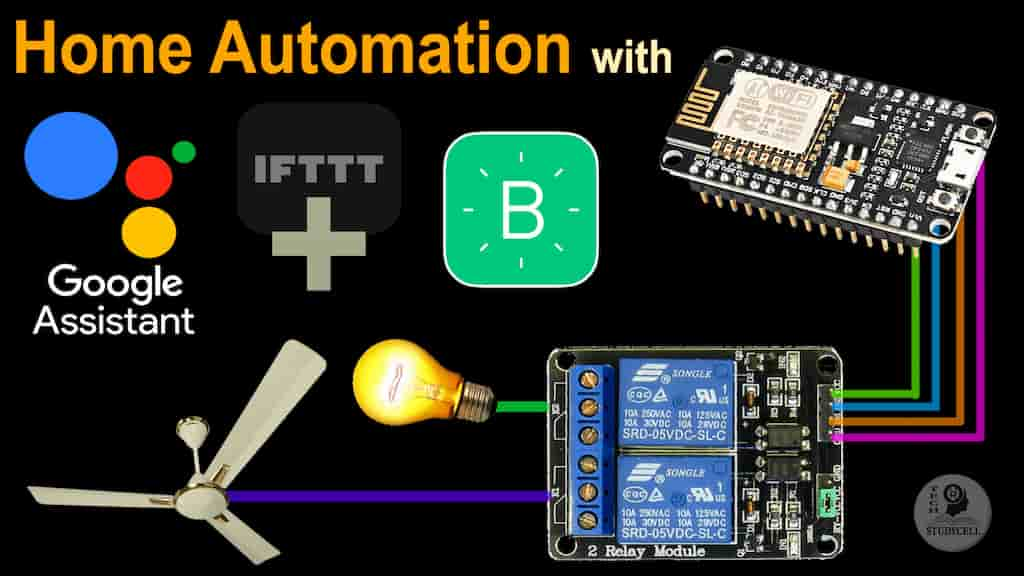
Apps and online services
Simply power on both the modules with the corresponding voltage mentioned above. Now, make the Din pin on transmitter high and you will find the Dout pin on receiver also goes high. You can have only one button on the sender side and one output on the receiver side. This will not help in building better projects, so we employ the encoder and decoder modules.

The design of the circuit is explained with respect to transmitter section and receiver section individually. The circuit diagram is divided in to the transmitter section and receiver section for easy understanding. The transmitter section of the project is shown on the following image. In this project, a simple but efficient home automation system using RF Module (Transmitter – Receiver pair) is designed. The system is designed with Arduino as the main processing unit.
Security Systems Engineer - Public vertical
First, we need to pull down the digital I/O pins 3 through 6 with the help of four 1KΩ resistors. Then connect four switches to these four pins with the other ends of the switches connected to 5V supply. We have previously explained the RF Transmitter and Receiver circuit in detail. Thanks to the quality BVS has been consistently striving towards for decades, we now work with several large control and drive manufacturers. As the only company worldwide working in the industrial electronics maintenance sector, we carry our status as "Bosch Rexroth Group Service Point", among others, with pride.
RF based system is useful if we have a large house where Bluetooth might go out of range. For example, if LOAD1_ON switch, which is connected to pin 6, is pressed, Arduino detects a logic HIGH at pin 6. Hence, Arduino sends a message as “@ABC$” via the RF transmitter. At the transmitter section, the Arduino continuously monitors the status of the switches . Whenever a switch is pressed, a logic HIGH is detected at that particular I/O pin. As a result, the Arduino transmits a suitable message corresponding to the switch pressed.
(Senior) System Engineer SAP Cloud Technologie Inhouse (all genders)
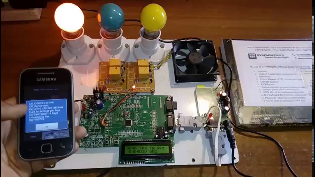
We will need a variable to store the message received by the HC-05 module, and variables mentioning the pins to which the LEDs are connected. Connect one terminal of the AC power supply to one terminal of the load. Connect the other terminal of the load to the common pin on the relay.
This four button key fob transmitter is also very productive for commercial uses in Industrial and medical systems. Remote controlled home automation system provides a simpler solution with RF technology. As technology is advancing so houses are also getting smarter. Modern houses are gradually shifting from conventional switches to centralized control system, involving RF controlled switches. Presently, conventional wall switches located in different parts of the house makes it difficult for the user to go near them to operate. Even more it becomes more difficult for the elderly or physically handicapped people to do so.
The remote controller circuit is just the RF transmitter section. The circuit connections of RF module are done as in set up of the basic model of RF Transmitter and Receiver. The address pins 1 to 8 of the encoder IC are hard wired to ground to assign the RF transmitter an address of 0x00. The pin 14 of the encoder IC which is active low is also hard-wired to ground to enable uninterrupted transmission of control signal to the RF receiver. The project RF based home automation system is developed to automate the use of conventional lighting mechanism in house by using RF controlled remote.
This project demonstrate the design and development of a Home Automation System Using RF Transceiver controlled by Arduino Micrcontroller. The user will remotely control various indoor appliances such as bulbs, doors and fans using Radio Frequency transmitter and receiver in home automation systems. It helps elderly people to control switches from anywhere up to 75 feet.
Thus the system serves a convenient way of lighting up the house without any physical movements. As mentioned earlier, we will be using two 5V relay module to control the AC loads. The term “5V” here represents the voltage required to trigger the relay. Out of the 4-data bit we will use only two in this project for demonstration purpose. You can use all four and control four AC Appliances with the same circuit. The Receiver module has four pins namely Vcc, Dout, Linear out and Ground as shown above.
Connect 5V from the microcontroller at the 10k ohm resistor, and connect GND to the open end of the photoresistor. Now, we can read the change in voltage by connecting a wire to the junction where the 10k ohm resistor and the photoresistor connects. To use a photoresistor as a light sensor we need to create a voltage divider. A photoresistor works by changing resistive value based on how much light is hitting the resistor.


No comments:
Post a Comment